
")
Altair has released the 2021.1-edition of Altair Inspire, the most user friendly topology optimisation software to generate and explore structurally efficient concepts in the earliest phases of the design process.
With version 2021.1, Inspire is entering a new phase. Inspire 2021.1 is now very close to a full-fledged CAD application and we expect less needing to switch back and forth between CAD and Inspire. A sketching capability similar to that of Altair Inspire Studio has been implemented. It can be used to draw accurate profiles driven by dimensions. In addition, all edits to the geometry are now stored in the Construction History so that they can easily be modified afterwards.
Availabilty
- Users with a valid license for Altair Inspire (Concept Engineer Units) can download and install version 2021.1 free of charge through their account at Altair One Marketplace.
- If you would like to try the software, you can This email address is being protected from spambots. You need JavaScript enabled to view it.. Please do not forget to include your full contact details.
- If you are convinced about Altair Inspire, you can contact us for the possibilities.
New Features
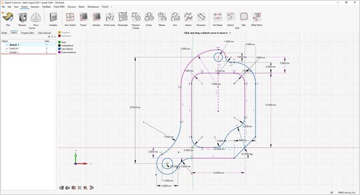
- Sketching
The new parametric sketching ribbon now features a constraints legend and a variety of new tools. You can apply variables when using most tools, and edit sketches using the new History Browser (F6).
- Constraints Legend - Inspire now provides feedback as to whether a sketch is under-constrained or over-constrained in the new sketch legend.
- Project - Project selected geometry onto the sketch plane.
- Intersect - Extract curves resulting from the intersection of the sketch plane with selected parts.
- Polygons - Sketch a regular polygon by defining the center and radius, or sketch a parallelogram by defining three corners.
- Ellipses - Sketch an ellipse by defining the center, width, and height. You can also create an open ellipse by adding start and end points.
- Splines - Sketch a spline curve using fit points or controls points. When using the Spline Through Points tool, the spline curve will pass through the sketch points. Splines Using Control Points will pass near, but not through, the sketch points.
- Dimensions - Apply and edit a dimensional constraint to control the size and proportions of a sketch entity.
- Extend - Extend or shorten a sketch entity.
- Fillet - Round the corners of a sketch entity to create fillets.
- Mirror - Mirror selected sketch entities about an axis.
- Offset - Offset selected sketch entities by clicking and dragging the original sketch.
- Geometry
The updated parametric Geometry ribbon now features new tools for Reference Geometry, Extract, and Shell. You can apply variables when using most tools, and edit geometry using the new History Browser (F6).
- Reference Geometry - Create reference planes, references axes, and reference points from geometry features or other reference entities.
- Extract - Extract selected geometry features and transfer them to a new part.
- Shell - Remove material and create thin walls to generate a shelled part.

- The Move tool has been updated so that moves can now be referenced.
- The Push/Pull tool now allows you to add, subtract, replace, or create a new part from the result of sketch face that has been pushed or pulled. The default is to add to the current part.
- The Keep Original and Instance options for the Mirror tool have been moved to the Find Options menu.
- The visualization for Boolean tools has been updated.
- The Cut tool has been renamed Slice.
- The Midsurface tool now remembers your previous selection for Mid vs. S1/S2.
- PolyNURBS
The updated parametric PolyNURBS ribbon now features new tools to move and mirror PolyNURBS bodies. PolyNURBS now retain all downstream geometry operations such as Booleans and fillets even after manipulating the cage. You can edit PolyNURBS using the new History Browser (F6).
- Move Bodies - Translate or rotate PolyNURBS bodies.
- Mirror Bodies - Mirror the bodies of a PolyNURBS part around a symmetry plane.
- Subdivision Surface - Select the Subdivision Surface check box in the upper right corner of the modeling window to maintain the part as a mesh-based subdivision surface rather than converting to NURBS surfaces. This makes it much faster to exit the tool, as it won’t perform the NURBS surface conversion.

- The Edit PolyNURBS tool has been removed, as editing is now handled through the History Browser.
- The Close tool has been renamed Repair.
- Structures
- Updates to Contact Gap and Penetration Values for SimSolid Analysis - The default contact settings are now the same for both the SimSolid and OptiStruct solvers.
- Reset Refine Results for SimSolid Analysis - You can now reset any SimSolid results you’ve refined in the Analysis Explorer.
- Section cuts can now be visualized in part color.
- Motion
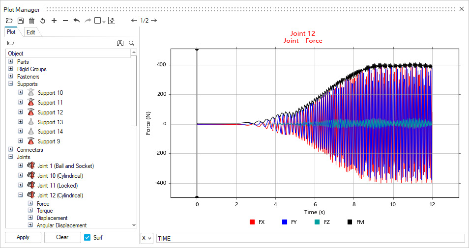
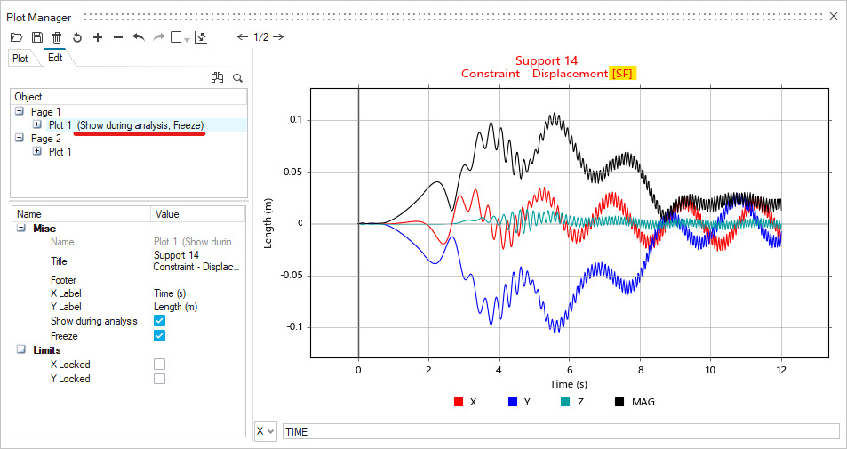
- Plot Manager Improvements - Improvements have been made to the Plot Manager for motion post-processing, including:
- Showing entity icons in the Plot Browser that can also reflect whether entity is currently hidden or not.
- Renaming of containers such as Supports (instead of Constraints) and Connectors (instead of Spiders) in the Plot Browser.
- Denoting when a plot has had Show during analysis or Freeze enabled.
- Automatically dismissing plots when exiting the Review Motion Results tool.
- Using an internally stored representation of plot template instead of using disk-based autosave operations.
- Improved template robustness for handling cases when some model entities have been suppressed.
- Parts List and Report File for Rigid Groups - The Rigid Groups table now includes a Parts column that lists the parts contained in each rigid group. Additionally, there are now buttons to save and view a rigid groups report file. This report contains more detailed information including the mass, mass moment of inertia, center of gravity location, and more.
- Lock Option for Spring Dampers - The Coil Spring and Torsion Spring microdialogs now have a Lock button similar to the lock feature for motors and actuators. When locked, the spring-dampers do not deform, and you can plot the Lock Force (for coil spring) and Lock Torque (for torsion spring) to understand the loading or to determine the preload required for the design position. For convenience, you can also find the Lock checkbox available on the context menu for springs, as a column in the springs table, as well as in the Property Editor under the General category. The locked state is also reported in the Model Browser and the Plot Browser in Plot Manager.
- Implicit Joint for Coil Springs - The Parallel Mounts Joint property for coil springs now offers a Translational implicit joint as an alternative to the previously available Cylindrical joint.
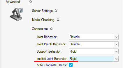
- Implicit Joint Behavior Setting - An option for specifying Implicit Joint Behavior has been added to the Run Settings dialog in the Connectors category under the Advanced section. Rigid is the default setting for implicit joint behavior.
- Export MDL with Plant Output Signals for Motion Contacts - The Provide Signals to Plant option is now available for motion contacts, but is disabled by default. It can be found in the Property Editor and when enabled, the motion export operation will include contact force output plant signals in the .mdl file for use in MotionView, MotionSolve, and Altair Activate
- Expanded range for damping in coil spring-dampers: We now allow entry of 0.0 for the coil spring damping rate. This is useful when you want to study the effect of having no damping without altering the spring-damper type.
- New filter buttons on Force Explorer: More buttons have been added to the Force Explorer for connectors and fasteners.
- Animation (H3D) file writing improvement: If enabled in the Motion Run Settings, this file will now be created even if you stop the run manually or if the run fails during the motion analysis.
- Jump to Contact Event improvement: The Jump to Contact Event buttons on the Force Explorer now work within the start and end times of the animation range specification.
- Plot Manager Improvements - Improvements have been made to the Plot Manager for motion post-processing, including:
- Print3D
- Improved Geometry Integration - Parametric geometry that is created in Inspire is now seamlessly integrated with Print3D. Edits made to geometry using construction history are carried over and automatically reflected in Print3D operations.
- Run Jobs on a Remote Server - You can now run jobs remotely on an Altair PBS server. You can also choose to locally run Print 3D jobs either sequentially or in parallel.